EdgeTX Logical and Function Switches (Part 3)
EdgeTX Cockpit Voice, part 3 of 9. Making a RadioMaster GX12 speak its own telemetry, so a low battery is something I hear instead of something I forgot to look at.
‹ Part 2: The Calibration Every Battery Warning Rests On · Part 4: What the Radio Actually Says › · Start at part 1
Part 1 established the goal and the one flight controller setting the whole thing rests on. This part is the machinery: how the radio decides when to speak, and how I keep three separate warning systems from fighting each other.
Three buttons, three colours, three subsystems
The GX12 has six extra buttons above the sticks. They are EdgeTX Customisable Function Switches (CFS), which means each one can be named, given a default state, and assigned an RGB colour that the radio actually lights up.
I use the second group of three, and I colour-coded them so I can confirm the state of the whole warning system with a glance at the radio, before I put the goggles on, which is the only moment I am actually looking at the radio.
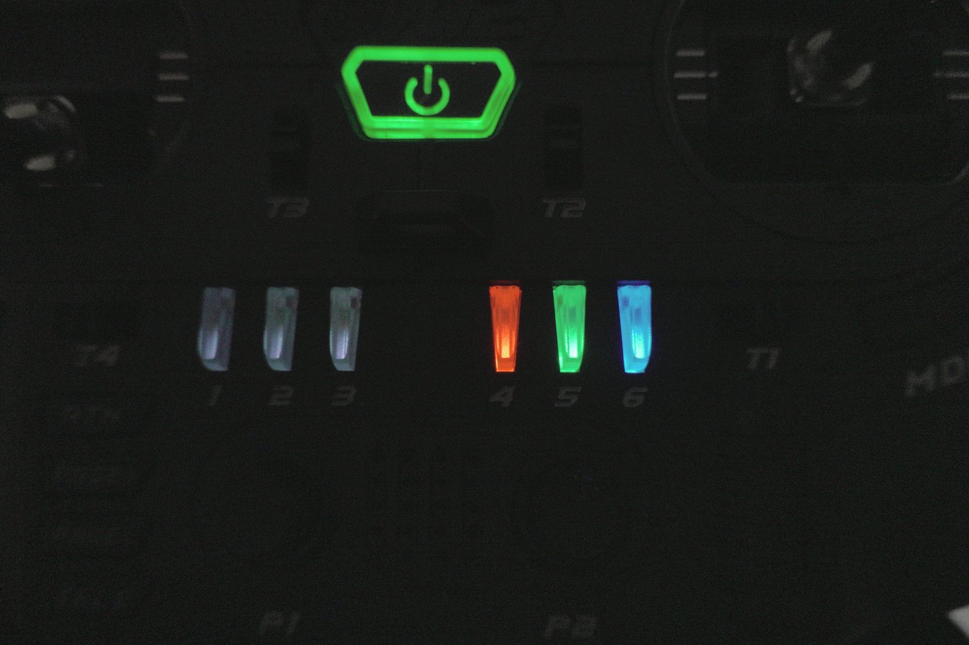
| Button | Name | Colour | Default | What it gates |
|---|---|---|---|---|
| SW4 | log | Red | Off | SD card telemetry recording |
| SW5 | bat | Green | On | All battery voltage warnings |
| SW6 | gps | Blue | Off | All GPS / satellite callouts |
Battery warnings default to on, that is the one I never want to have to remember. GPS callouts default to off, because on the whoops and the analog rippers there is no GNSS module at all and I do not want a "GPS lost" siren on every flight. Logging defaults to off because it fills the SD card.
Here is the part that took me a while to work out: on the GX12, the per-model
CFS block overrides the radio-level switch config. Both files have entries for
SW4/5/6. The radio-level one in radio.yml is the fallback; the per-model
customSwitches block in the model YAML is what actually runs.
 1# model00.yml — this is the block that wins
 2customSwitches:
 3   SW4:
 4      name: "log"
 5      type: 2POS
 6      group: 0              # 0 = independent toggle
 7      start: START_OFF
 8      onColor:  { r: 63, g:  0, b:  0 }   # red
 9      offColor: { r:  2, g:  2, b:  2 }
10   SW5:
11      name: "bat"
12      type: 2POS
13      group: 0
14      start: START_ON       # battery warnings armed by default
15      onColor:  { r:  0, g: 40, b:  2 }   # green
16      offColor: { r:  4, g:  0, b:  0 }
17   SW6:
18      name: "gps"
19      type: 2POS
20      group: 0
21      start: START_OFF
22      onColor:  { r:  0, g:  0, b: 63 }   # blue
23      offColor: { r:  2, g:  2, b:  2 }
group: 0 means independent toggle. My SW1/SW2/SW3 sit in group: 1, which
makes them behave like mutually-exclusive radio buttons, useful for things like
selecting a VTX power level, wrong for three independent warning subsystems.
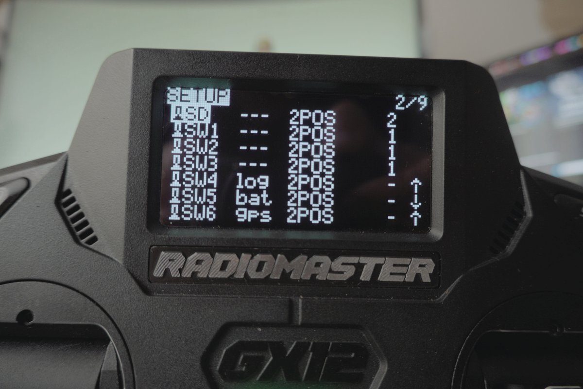
Once the buttons are named, EdgeTX shows the names everywhere instead of
SW52, which makes the logical switch page readable:
The signal chain
Before the tables, here is the whole path from a cell to a sound:
flowchart LR
    subgraph AIR["Aircraft"]
      direction TB
      GNSS["GNSS module"]
      FC["Betaflight FC<br /><code>report_cell_voltage = ON</code>"]
      GNSS --> FC
      FC -->|"CRSF 0x08 battery<br />CRSF 0x02 GPS"| RX["ELRS RX"]
    end

    RX -.->|"2.4 GHz downlink<br />telemetry ratio 1:N"| TX["ELRS TX module"]

    subgraph GX12["RadioMaster GX12 — EdgeTX 2.12.2"]
      direction TB
      TX --> SENS["Telemetry sensors<br />RxBt · Sats · GAlt"]
      BTN["CFS buttons<br />log · bat · gps"]
      SENS --> LS["Logical switches<br />L1 … L11"]
      BTN -->|AND gate| LS
      LS --> SF["Special functions"]
      SF --> SPK(["Speaker"])
      SF --> SD[("SD card CSV")]
    end
The key structural idea is the AND gate. Every logical switch has an
andsw field, a second condition that must also be true. That is what turns
eleven independent threshold detectors into three switchable subsystems. The
threshold logic and the arming logic are cleanly separated, and I never have to
edit thresholds to silence a subsystem.
The logical switches
Eleven of them. Screens first, then the YAML, then what each one is for.
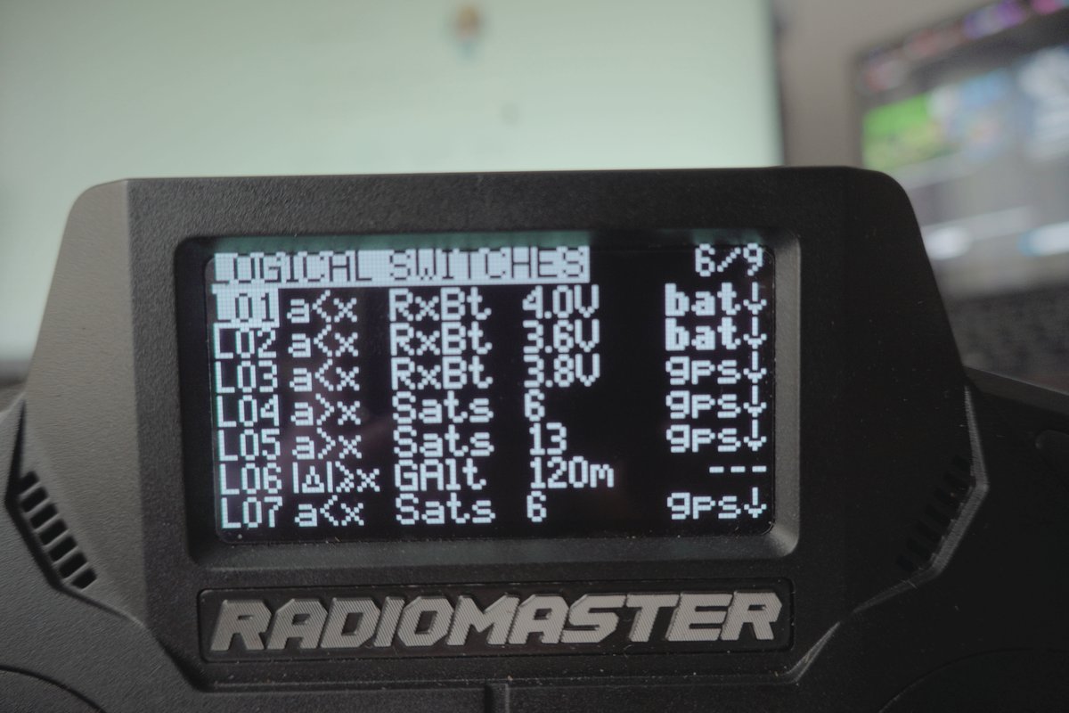
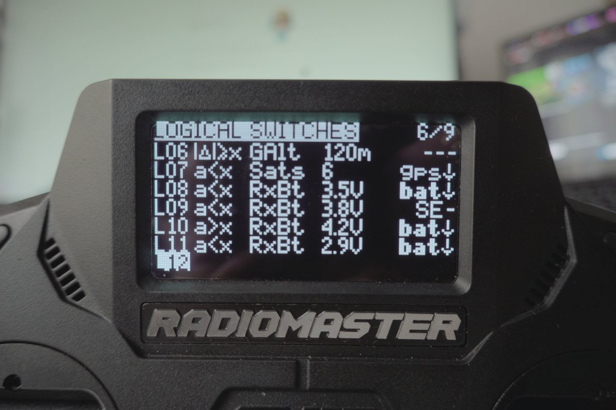
One mapping detail that will save you confusion if you read the YAML: the
logicalSw block is zero-indexed while the UI labels are one-indexed.
logicalSw: 2: is the switch the radio calls L3. Likewise tele(14) is a
zero-based index into the telemetrySensors list, in my file that is RxBt.
 1logicalSw:
 2   0:                              # = L1
 3      func: FUNC_VNEG              # a < x
 4      def: "tele(14),40"           # RxBt < 4.0 V   (prec:1, so 40 = 4.0)
 5      andsw: "SW52"                # AND  bat button on
 6   1:                              # = L2
 7      func: FUNC_VNEG
 8      def: "tele(14),36"           # RxBt < 3.6 V
 9      andsw: "SW52"
10   2:                              # = L3   <-- the one that saves flights
11      func: FUNC_VNEG
12      def: "tele(14),38"           # RxBt < 3.8 V
13      andsw: "SW62"                # AND  gps button on
14   3:                              # = L4
15      func: FUNC_VPOS              # a > x
16      def: "tele(22),6"            # Sats > 6
17      andsw: "SW62"
18   4:                              # = L5
19      func: FUNC_VPOS
20      def: "tele(22),13"           # Sats > 13
21      andsw: "SW62"
22   5:                              # = L6
23      func: FUNC_ADIFFEGREATER     # |delta| >= x   <-- read the note below
24      def: "tele(21),120"          # GAlt, 120 m
25      andsw: "NONE"                # always armed
26   6:                              # = L7
27      func: FUNC_VNEG
28      def: "tele(22),6"            # Sats < 6
29      andsw: "SW62"
30   7:                              # = L8
31      func: FUNC_VNEG
32      def: "tele(14),35"           # RxBt < 3.5 V
33      andsw: "SW52"
34   8:                              # = L9
35      func: FUNC_VNEG
36      def: "tele(14),38"           # RxBt < 3.8 V
37      andsw: "SE1"                 # SE middle -- prearm gate, see below
38   9:                              # = L10
39      func: FUNC_VPOS
40      def: "tele(14),42"           # RxBt > 4.2 V
41      andsw: "SW52"
42   10:                             # = L11
43      func: FUNC_VNEG
44      def: "tele(14),29"           # RxBt < 2.9 V
45      andsw: "SW52"
Every single one of these has delay: 0 and duration: 0. Hold that thought.
That is the whole structure. Eleven threshold detectors, three switchable subsystems, one AND slot doing the separating. What none of it does yet is make a sound.
Series: EdgeTX Cockpit Voice, part 3 of 9. Making a RadioMaster GX12 speak its own telemetry, so a low battery is something I hear instead of something I forgot to look at.
‹ Part 2: The Calibration Every Battery Warning Rests On · Part 4: What the Radio Actually Says › · Start at part 1